Directional couplers are among the most used building blocks in silicon photonics, and among the most polarization dependent. A silicon wire is wider than it is tall, so TE and TM light couple across the gap at different rates, and a coupler that fully crosses TE sends much of the TM light out of the wrong port.
In a recent paper, Jihwan You, Dohun Koh and colleagues in Prof. Sangsik Kim's group at KAIST remove this dependence by building both waveguides from subwavelength gratings (SWGs) and tilting the bars [1]. Here, we reproduce their design flow in Tidy3D, from an effective-medium model to full 3D FDTD of the final device.
The device
Parameter | Value |
|---|---|
Silicon waveguides, width / height | 500 nm / 300 nm, SiO₂ cladding |
Gap, edge to edge | 700 nm |
Grating period (normal to the bars) / duty cycle | 220 nm / 0.5 |
Bar tilt | +θ in one waveguide, −θ in the other |
Coupling length | 34 µm, including two 2 µm wedge tapers |
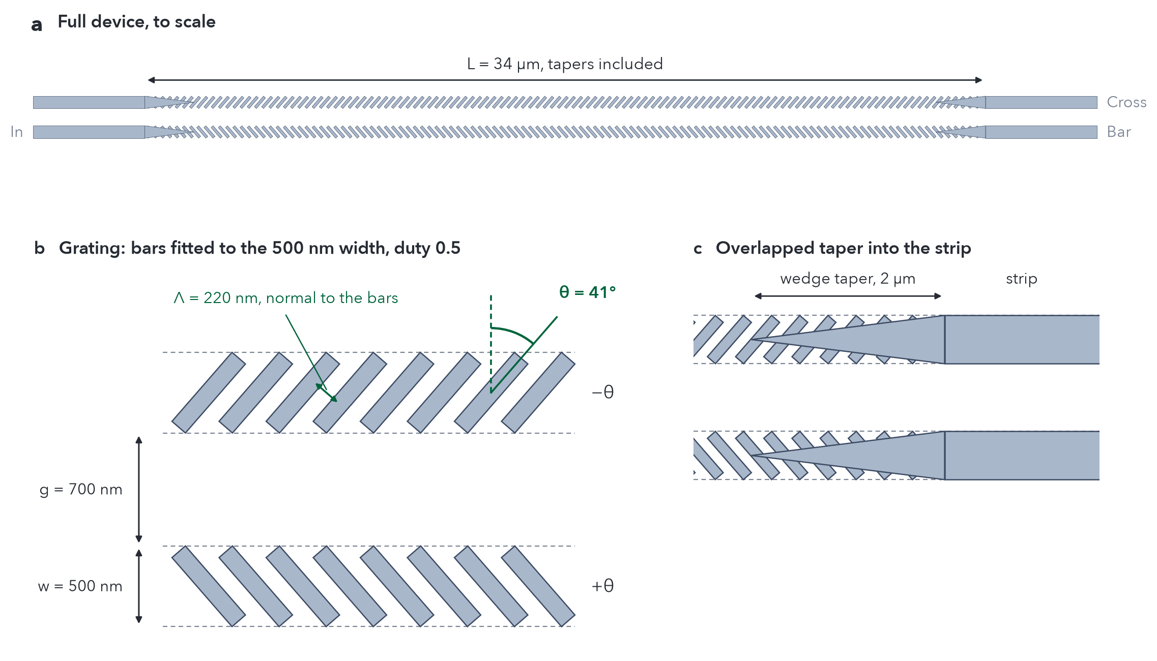
Figure 1. The coupler at θ = 41°. (a) The full device to scale; light enters the lower waveguide and, in the cross state, leaves from the upper one. (b) The bars are rotated rectangles lengthened until their corners touch the waveguide edges. (c) A strip wedge over the full-width grating converts the strip mode into the grating mode.
How the tilt balances TE and TM
With a 220 nm period, well below the Bragg period at 1550 nm, light sees the grating as an anisotropic metamaterial. A field along the bars sees the parallel average of the silicon and oxide permittivities, and a field across them sees the series average:

With f = 0.5, n∥ = 2.66 and n⊥ = 1.89. Tilting the bars by θ rotates this anisotropy in the plane of the chip. The TM mode's dominant field points up, along every bar, and keeps seeing n∥. The TE mode's in-plane field points more and more across the bars and sees

As the TE index drops, the TE mode spreads further into the gap and couples faster, so its coupling length falls while TM's barely changes, and the two meet at one angle (Figure 2). The opposite tilts in the two waveguides keep the coupler mirror-symmetric, so the power transfer can be complete.
Following the paper, we first modeled each grating as a homogeneous core with FullyAnisotropicMedium and computed its supermodes with the Tidy3D mode solver. This puts the balance at 46.9°, with a coupling length of 36.5 µm.
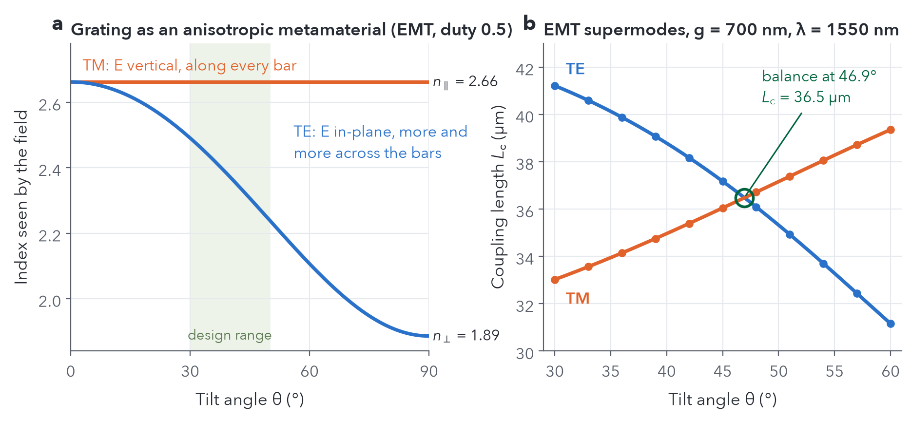
Figure 2. (a) Index seen by the dominant field of each polarization as the bars tilt. (b) Coupling lengths of the effective-medium coupler from the Tidy3D mode solver.
Finding the angle with FDTD
The effective-medium model ignores the finite period and the shape of the bars, so the angle has to come from full-wave simulation. We simulated one long grating section per angle and polarization, with flux monitors every 1 µm, which gives the power left in the input waveguide versus distance in a single run (Figure 3a). Scanning 30° to 50° for both polarizations took 22 simulations and 71 FlexCredits. The coupling lengths meet at 40.9°, at 33.1 µm (Figure 3b).
Two details of the scan are worth noting. The TM grating mode has long vertical tails, so the transverse domain matters: on a 4 × 3 µm domain, the absorbers clip those tails, the TM coupling length comes out 1 µm too long, and the balance moves to 38.7°. On 7 × 5 µm, the result no longer changes (we checked TM against a 10 × 8 µm domain). The effective-medium balance sits 6° higher than FDTD, and most of that difference is in TE, whose field crosses the bars: near 40°, its effective-medium coupling length is 5.4 µm too long, against 2.0 µm for TM.
Our balance angle sits a few degrees above the paper's design angle, and the difference is in TE alone: our TM coupling lengths agree closely with the paper's, but our TE ones are about 1 µm longer. Neither the domain nor the mesh explains this; refining the mesh from 30 to 15 nm moves the balance by half a degree at most. The likely cause is the bar ends, to which TE is especially sensitive because its field crosses the sidewalls: pulling the bar corners 10 nm in from the sidewalls shortens the TE coupling length by 2.3 µm, against 1.0 µm for TM.
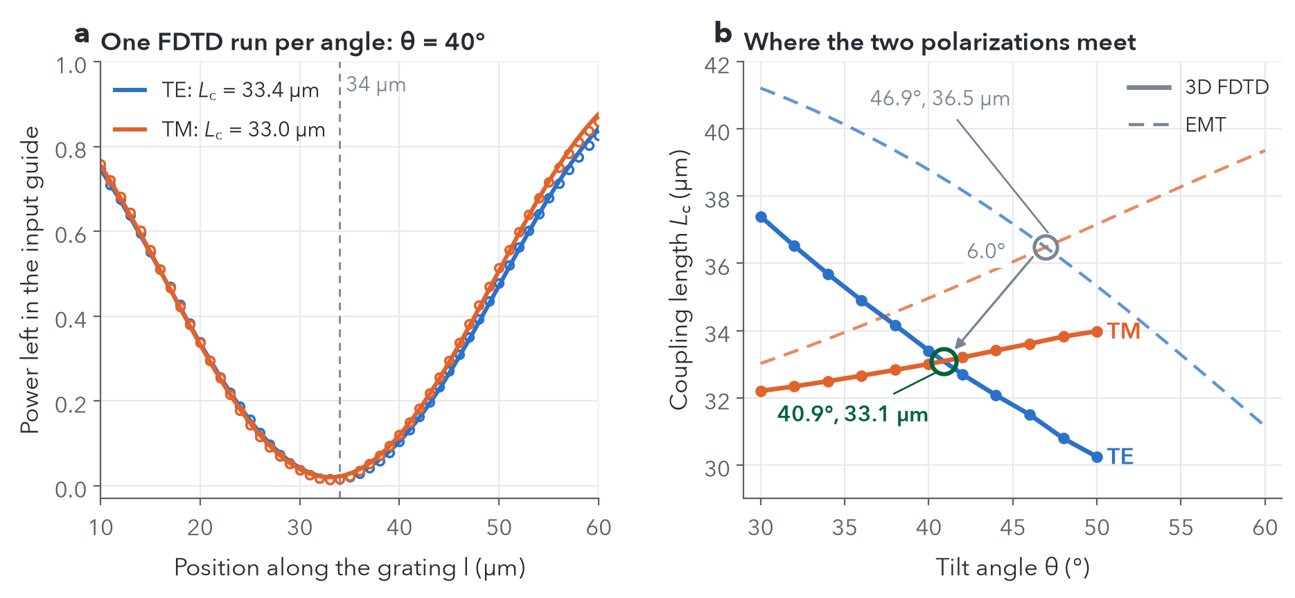
Figure 3. (a) Power remaining in the input waveguide along the grating at θ = 40°, from one FDTD simulation per polarization, with cos² fits. (b) Coupling length versus tilt angle from 3D FDTD (solid) and the effective-medium model (dashed).
The full device
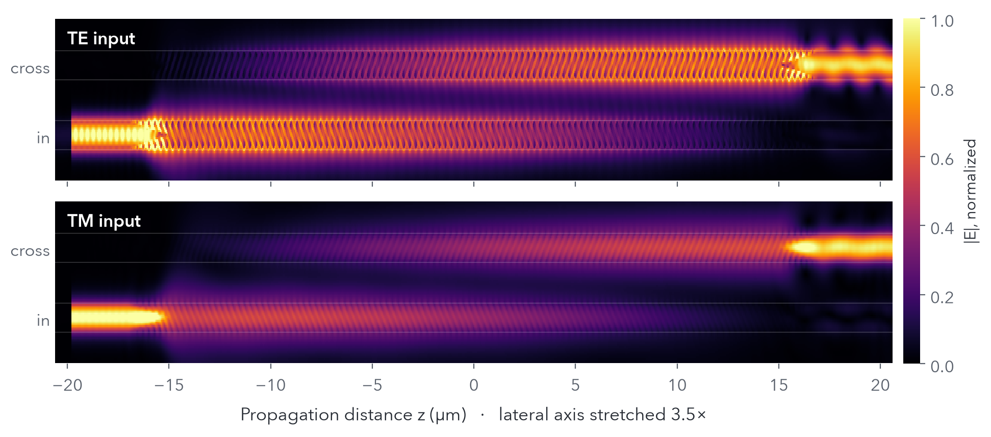
We then simulated the complete 34 µm coupler, tapers included, from 1450 to 1650 nm, and recorded the total power in each output waveguide, as the paper does. At 1550 nm, both polarizations cross over (Figure 4).
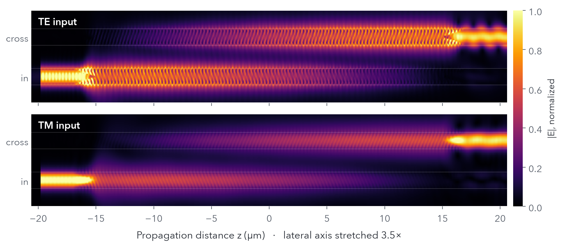
Figure 4. |E| in the silicon mid-plane at 1550 nm for TE (top) and TM (bottom) input, θ = 41°. The lateral axis is stretched 3.5×.
The spectra show the tilt at work (Figure 5). At 41°, the TE and TM bar dips sit at 1550 and 1547 nm, the bar port stays below −10 dB from 1500 to 1600 nm for both polarizations, and the cross port is within 0.7 dB of the input at 1550 nm. At 30° and 46°, the dips separate in opposite directions: each degree of tilt moves the TE dip by about −2.9 nm and the TM dip by +0.8 nm.
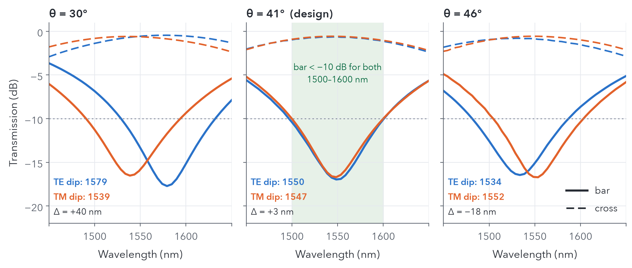
Figure 5. Bar (solid) and cross (dashed) transmission, total power, at three tilt angles with L = 34 µm. The shaded band marks where the bar port is below −10 dB for both polarizations.
Conclusion
Tilting the bars of a subwavelength grating gives a single-parameter handle on polarization: it lowers the index seen by TE's in-plane field and leaves TM's vertical field alone. The effective-medium model explains the trend and gives a starting point, but the design angle has to come from full-wave simulation, with enough room around the grating for TM's long tails. In Tidy3D, that lands the balance at 40.9°, where both polarizations cross over in the same 34 µm coupler.
Reproducibility and references
Download all eight Python scripts (ZIP)
The scripts used for these results: swg_dc.py (geometry and FDTD setup), emt_theta0.py, emt_tilt.py and emt_sweep.py (effective-medium supermodes), lc_scan.py (coupling-length scan), domain_check.py (the runs on the 7 × 5 µm domain: scan, spectra and field maps), paper_gap.py (the mesh and bar-end checks) and make_figures.py (figures).
1. J. You, D. Koh, S. Lee, M. Lee, H. Kim, and S. Kim, "Polarization-independent directional coupler using tilted subwavelength gratings," J. Opt. Soc. Am. B 43, 2537 (2026). https://doi.org/10.1364/JOSAB.612181
2. Tidy3D documentation: FullyAnisotropicMedium
3. Tidy3D example: Broadband polarization beam splitter using anisotropic metamaterial